Wednesday, March 20, 2013

Nodal analysis


In electric circuits analysis, nodal analysisnode-voltage analysis, or the branch current method is a method of determining the voltage (potential difference) between "nodes" (points where elements or branches connect) in an electrical circuit in terms of the branch currents.
In analyzing a circuit using Kirchhoff's circuit laws, one can either do nodal analysis using Kirchhoff's current law (KCL) or mesh analysis using Kirchhoff's voltage law (KVL). Nodal analysis writes an equation at each electrical node, requiring that the branch currents incident at a node must sum to zero. The branch currents are written in terms of the circuit node voltages. As a consequence, each branch constitutive relation must give current as a function of voltage; an admittance representation. For instance, for a resistor, Ibranch = Vbranch * G, where G (=1/R) is the admittance (conductance) of the resistor.
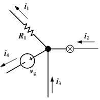
Nodal analysis is possible when all the circuit elements' branch constitutive relations have an admittance representation. Nodal analysis produces a compact set of equations for the network, which can be solved by hand if small, or can be quickly solved using linear algebra by computer. Because of the compact system of equations, many circuit simulation programs (e.g. SPICE) use nodal analysis as a basis. When elements do not have admittance representations, a more general extension of nodal analysis, modified nodal analysis, can be used.
While simple examples of nodal analysis focus on linear elements, more complex nonlinear networks can also be solved with nodal analysis by using Newton's method to turn the nonlinear problem into a sequence of linear problems.

Method

  1. Note all connected wire segments in the circuit. These are the nodes of nodal analysis.
  2. Select one node as the ground reference. The choice does not affect the result and is just a matter of convention. Choosing the node with the most connections can simplify the analysis.
  3. Assign a variable for each node whose voltage is unknown. If the voltage is already known, it is not necessary to assign a variable.
  4. For each unknown voltage, form an equation based on Kirchhoff's current law. Basically, add together all currents leaving from the node and mark the sum equal to zero. Finding the current between two nodes is nothing more than "the node you're on, minus the node you're going to, divided by the resistance between the two nodes."
  5. If there are voltage sources between two unknown voltages, join the two nodes as a supernode. The currents of the two nodes are combined in a single equation, and a new equation for the voltages is formed.
  6. Solve the system of simultaneous equations for each unknown voltage.

Examples

[edit]Basic case

Basic example circuit with one unknown voltage, V1.
The only unknown voltage in this circuit is V1. There are three connections to this node and consequently three currents to consider. The direction of the currents in calculations is chosen to be away from the node.
  1. Current through resistor R1: (V1 - VS) / R1
  2. Current through resistor R2: V1 / R2
  3. Current through current source IS: -IS

With Kirchhoff's current law, we get:
\frac{V_1 - V_S}{R_1} + \frac{V_1}{R_2} - I_S = 0
This equation can be solved in respect to V1:
V_1 = \frac{\left( \frac{V_S}{R1} + I_S \right)}{\left( \frac{1}{R_1} + \frac{1}{R_2} \right)}
Finally, the unknown voltage can be solved by substituting numerical values for the symbols. Any unknown currents are easy to calculate after all the voltages in the circuit are known.
V_1 = \frac{\left( \frac{5\text{ V}}{100\,\Omega} + 20\text{ mA} \right)}{\left( \frac{1}{100\,\Omega} + \frac{1}{200\,\Omega} \right)} \approx 4.667\text{ V}

Monday, May 24, 2010

Dynamo

"Dynamo Electric Machine" (end view, partly section, U.S. Patent 284,110)

A dynamo, originally another name for an electrical generator, now means a generator that produces direct current with the use of a commutator. Dynamos were the first electrical generators capable of delivering power for industry, and the foundation upon which many other later electric-power conversion devices were based, including the electric motor, the alternating-currentalternator, and the rotary converter. They are rarely used for power generation now because of the dominance of alternating current, the disadvantages of the commutator, and the ease of converting alternating to direct current using solid state methods.

The word still has some regional usage as a replacement for the word generator. A small electrical generator built into the hub of a bicycle wheel to power lights is called a Hub dynamo, although these are invariably AC devices.

Description

The dynamo uses rotating coils of wire and magnetic fields to convert mechanical rotation into a pulsing direct electric current throughFaraday's law. A dynamo machine consists of a stationary structure, called the stator, which provides a constant magnetic field, and a set of rotating windings called the armature which turn within that field. On small machines the constant magnetic field may be provided by one or more permanent magnets; larger machines have the constant magnetic field provided by one or more electromagnets, which are usually called field coils.

The commutator was needed to produce direct current. When a loop of wire rotates in a magnetic field, the potential induced in it reverses with each half turn, generating an alternating current. However, in the early days of electric experimentation, alternating current generally had no known use. The few uses for electricity, such as electroplating, used direct current provided by messy liquid batteries. Dynamos were invented as a replacement for batteries. The commutator is a set of contacts mounted on the machine's shaft, which reverses the connection of the windings to the external circuit when the potential reverses, so instead of alternating current, a pulsing direct current is produced.

Historical milestones

Faraday's disc

The first electric generator was invented by Michael Faraday in 1831, a copper disk that rotated between the poles of a magnet. This was not a dynamo because it did not use a commutator. However, Faraday's disk generated very low voltage because of its single current path through the magnetic field. Faraday and others found that higher, more useful voltages could be produced by winding multiple turns of wire into a coil. Wire windings can conveniently produce any voltage desired by changing the number of turns, so they have been a feature of all subsequent generator designs, requiring the invention of the commutator to produce direct current.


Siemens and Wheatstone dynamo (1867)

The first practical designs for a dynamo were announced independently and simultaneously by Dr. Werner Siemens and Charles Wheatstone. On January 17, 1867, Siemens announced to the Berlin academy a "dynamo-electric machine" (first use of the term) which employed a self-powering electromagnetic armature.[4] On the same day that this invention was announced to the Royal Society Charles Wheatstone read a paper describing a similar design with the difference that in the Siemens design the armature was in series with the rotor, but in Wheatstone's design it was in parallel.[5] The use of electromagnets rather than permanent magnets greatly increases the power output of a dynamo and enabled high power generation for the first time. This invention led directly to the first major industrial uses of electricity. For example, in the 1870s Siemens used electromagnetic dynamos to power electric arc furnaces for the production of metals and other materials.

Discovery of electric motor principles

While not originally designed for the purpose, it was discovered that a dynamo can act as anelectric motor when supplied with direct current from a battery or another dynamo. At an industrial exhibition in Vienna in 1873, Gramme noticed that the shaft of his dynamo began to spin when its terminals were accidentally connected to another dynamo producing electricity. Although this wasn't the first demonstration of an electric motor, it was the first practical one. It was found that the same design features which make a dynamo efficient also make a motor efficient. The efficient Gramme design, with small magnetic air gaps and many coils of wire attached to a many-segmented commutator, also became the basis for the design of all practical DC motors.

Large dynamos producing direct current were problematic in situations where two or more dynamos are working together and one has an engine running at a lower power than the other. The dynamo with the stronger engine will tend to drive the weaker as if it were a motor, against the rotation of the weaker engine. Such reverse-driving could feed back into the driving engine of a dynamo and cause a dangerous out of control reverse-spinning condition in the lower-power dynamo. It was eventually determined that when several dynamos all feed the same power source all the dynamos must be locked into synchrony using a jackshaft interconnecting all engines and rotors to counter these imbalances.


Dynamo as commutated DC generator

After the discovery of the AC Generator and that alternating current can in fact be useful for something, the word dynamo became associated exclusively with the commutated DC electric generator, while an AC electrical generator using either slip rings or rotor magnets would become known as an alternator.

An AC electric motor using either slip rings or rotor magnets was referred to as a synchronous motor, and a commutated DC electric motor could be called either an electric motor though with the understanding that it could in principle operate as a generator.


Rotary converter development

After dynamos and motors were found to allow easy conversion back and forth between mechanical or electrical power, they were combined in devices called rotary converters, rotating machines whose purpose was not to provide mechanical power to loads but to convert one type of electric current into another, for example DC into AC. They were multi-field single-rotor devices with two or more commutators, one to provide power to one set of armature windings to turn the device, and one or more attached to other windings to produce the output current.

The rotary converter can directly convert, internally, any type of electric power into any other. This includes converting beween direct current (DC) and alternating current (AC), three phase and single phase power, 25 cycle AC and 60 cycle AC, or many different output voltages at the same time. The size and mass of the rotor was made large so that the rotor would act as a flywheel to help smooth out any sudden surges or dropouts in the applied power.

The technology of rotary converters was replaced in the early 20th century by vacuum tube circuits, which were smaller, did not produce vibration and noise, and required less maintenance. The same conversion tasks are now performed by solid state power semiconductor


Jedlik's dynamo

The native form of this personal name is Jedlik Ányos István. This article uses the Western name order.
Ányos Jedlik

Ányos Jedlik
BornJanuary 11, 1800
Szímő, Kingdom of Hungary
DiedDecember 13, 1895
Győr, Kingdom of Hungary,Austria-Hungary
CitizenshipHungarian
NationalityHungarian
Fieldsinventor, engineer, physicist
Known forDynamo

Stephen Ányos Jedlik (Hungarian: Jedlik Ányos István, in older texts and publications: Latin:Anius or: Anianus Jedlik) (January 11, 1800 – December 13, 1895) was a Hungarian inventor,engineer, physicist, Benedictine priest. He was also member of the Hungarian Academy of Sciences, and author of several books. He is considered by Hungarians and Slovaks to be the unsung father of the dynamo and electric motor. Today he is the pride of both the Slovak and Hungarian nations.

He was born in a Hungarian village Szimő, Kingdom of Hungary, (today Zemné, Slovakia). Jedlik's education began at high schools in Nagyszombat (today Trnava) and Pozsony (today Bratislava). In 1817 he became a Benedictine and from that time continued his studies at the schools of that order. He lectured at Benedictine schools up to 1839, then for 40 years at the Budapest University of Sciencesdepartment of physics-mechanics. Only few guessed at that time that his beneficial activities would play an important part in bringing up a new generation of physicists.

In 1845 he began teaching his pupils in Hungarian instead of Latin. His cousin Gergely Czuczor (famous Hungarian linguist) asked him to create the first Hungarian vocabulary in physics. Through his textbook he is regarded as one of the establishers of Hungarian vocabulary in physics. He became the dean of the faculty of arts in 1848, and by 1863 he was rector of the University. {{imagestack|

Jedlik's "lightning-magnetic self-rotor", 1827 (The world's first electric motor)
The Jedlik Dynamo

From 1858 he was a corresponding member of theHungarian Academy of Sciences and from 1873 an honorary member. He preceded his contemporaries in his scientific work, but he did not speak about his most important invention, his prototype dynamo, until 1856; it was not until 1861 that he mentioned it in writing in a list of inventory of the university. Although that document might serve as a proof of Jedlik's status as the originator, the invention of the dynamo is linked to Siemens' name because Jedlik's invention did not rise to notice at that time. Later still he invented an electrostatic machine, which was an early form of the impulse generators now applied in nuclear research.

In 1827, he started experimenting with electromagnetic rotating devices which he called lightning-magnetic self-rotor. In the prototype both the stationary and the revolving parts were electromagnetic. In 1873 at the World's Fair in Vienna he demonstrated his lighting conductor.

After his retirement he continued working and spent his last years in complete seclusion at the priory in Győr, the Kingdom of Hungary, Austria-Hungary where he died.


Dynamo invention

Drawn plan of a "telephon" by Ányos Jedlik in Hungarian. Pannonhalma Archabbey, Kingdom of Hungary

Ányos Jedlik's best known invention is the principle ofdynamo self-excitation.

In 1827, Jedlik started experimenting with electromagnetic rotating devices which he called electromagnetic self-rotors.

In the prototype of the single-pole electric starter, both the stationary and the revolving parts were electromagnetic. In essence, the concept is that instead of permanent magnets, two electromagnets opposite to each other induce the magnetic field around the rotor. He formulated the concept of the self-excited dynamo about 1861, six years prior to Siemens andWheatstone.

As one side of the coil passes in front of the north pole, crossing the line of force, current is thus induced. As the frame rotates further the current diminishes, then arriving at the front of the south pole it rises again but flows in the opposite direction. The frame is connected to a commutator, thus the current always flows in the same direction in the external circuit.

Electrical generator

In electricity generation, an electric generator is a device that converts mechanical energy to electrical energy. The reverse conversion of electrical energy into mechanical energy is done by amotor; motors and generators have many similarities. A generator forces electrons in the windings to flow through the externalelectrical circuit. It is somewhat analogous to a water pump, which creates a flow of water but does not create the water inside. Thesource of mechanical energy may be a reciprocating or turbinesteam engine, water falling through a turbine or waterwheel, aninternal combustion engine, a wind turbine, a hand crank,compressed air or any other source of mechanical energy.

Historical developments

Before the connection between magnetism and electricity was discovered, electrostatic generatorswere invented that used electrostatic principles. These generated very high voltages and lowcurrents. They operated by using moving electrically charged belts, plates and disks to carry charge to a high potential electrode. The charge was generated using either of two mechanisms:

Because of their inefficiency and the difficulty of insulating machines producing very high voltages, electrostatic generators had low power ratings and were never used for generation of commercially-significant quantities of electric power. The Wimshurst machine and Van de Graaff generator are examples of these machines that have survived.

WORLD ENERGY SIMULATOR (model 1) FOR WIN 95/98/ME/NT4.x/2000/XP & POWERMACS (educational program)

This is a 'game-style' simulator that puts the student in control of the Supply and Demand for energy throughout the world. Each of 6 regions must be maintained based on choices of Scenario which include factors such as population and economic growth rates, undiscovered resources, efficiency improvements, etc. The goal is to reach a point in the future where the energy demands can be met totally with renewable energy resources. Students are rated on whether they can minimize shortages and environmental damage. Text and animated tutorials are included along with built in instructions for play.

The resolution and color requirements are restricted--see REQUIREMENTS.

REQUIREMENTS: Win 95/98/ME/NT4.x/2000/XP, a Pentium level processor (166 MHz or faster is recommended), a video card displaying at 1024x768 or 800x600 screen resolutions and in high-color (15-16 bit) or true-color (24-32 bit) color depths. Memory requirements of 32-64 Megs are recommended--on slow machines and those with less than 32 Megs of memory, a special graphics mode can be setup to speed execution and reduce memory problems. POWERMACS--G3 or G4 is recommended but will run on most older models. 1024x768 or 800x600 resolution is required and thousands or millions of colors.

Download link:
click here!